Nomad 3D Editor
Workflow
The typical workflow in the editor is to modify the model in order to make it consistent with its axes, and then to add and set up the axes.
Model
Each component of the model can be linked to one axis (translational or rotational). This axis will move this component and all its descendants. Therefore the components of a model must be regrouped in regard to their axes dependencies.
Some components may be regrouped as a single part (due to the conception processes of an industrial SolidWorks model). This can be an issue if several axes belong to this group (example : a goniometer). In these case the component must be subdivided. For now the subdivision of the mesh itself must be done in a third-party software (for instance Blender, but any 3D modeling software supporting STL import/export can be used). In the editor, the subdivided component will have its geometry removed and children components will be added for every provided parts. The total geometry of the component before and after the subdivision should be consistent.
In order to have a model as light as possible eventually, all the components that are not visible, doubled or useless for any reason should be removed.
Usage
The editor is launched using the java jvm. A Nomad server with the configuration of the instrument must run. The editor can then be launched:
> java -jar target/nomad-3d-editor-0.0.1-SNAPSHOT.jar tcp://localhost:7000:n3dInterface
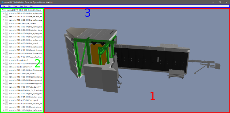
The editor interface is composed of 3 parts :
- 3D view of the model of the instrument.
- Hierarchical view of the components of the model.
- Menu bar.
Controls
General
- Help > Camera : Shows the help for the movements.
- View > Level of detail : Selects the displayed level of detail.
- Ctrl + mouse : Changes the speed of the camera.
Mouse
The components can be manually moved around their axis by clicking them with mouse left and dragging the mouse.
The camera is controlled by the mouse :
- Middle click + drag : Rotate around the point of reference.
- Right click + drag : Translate in the view plane.
- Scroll up : Zoom in.
- Scroll down : Zoom out.
- Control down : Increase the sensitivity of translation and zoom.
- Shift down : Decrease the sensitivity of translation and zoom.
Selection
- Ctrl + click left : Selects a leaf component. To obtain the parent hierarchy, a - appears in all the parents, then we can click on a parent to select the hierarchy.
- A : Selects everything or nothing.
- S : Toggles to a state where the components are selected when the mouse is over.
- D : Reverses, unselects.
- W : Once selected, the components become walls.
The components can be selected either in the 3D view by pressing ctrl + left click or by checking their item in the tree view. When a component is selected in the tree view, all its descendants are selected. The 3D view selection only selects leaf components.
Some operations are applied to the selected component(s). In these case, the considered component are the ones that are one the top or their selected hierarchy (ie the roots of the forest defined by all the subtrees in the selection).
Components
If the hierarchy of the components does not suit the axes, it must be recreated. We select a set of components that will move "together".
- Edit > Components > Regroup components : A new component is created grouping the selected components. Some options allow to do different type of regroupment.
- Edit > Components > Insert component : The new component is inserted as child of the selected component.
- Edit > Components > Remove component : The selected component is removed.
- Edit > Components > Subdivide component :
- Find the leaf component to subdivide and edit the associated STL file (in the exported folder, i.e. with maximum level of detail). Use Blender or another tool, resulting in N STL files.
- Use the subdivide interface to add the N files giving a name to the new components.
Note : When a component has not the good parent, the move operation can be realized whereas it is not implemented :
- Select the component and another one at the same level in the target hierarchy.
- Regroup the components with parent of set as the future common parent, unchecking Insert new because it is useless.
Axes
An axis is edited through 3 successive phases :
- Definition : Define the type, direction, position of the axis.
- Calibration : Define the median value (ie the zero value) and the min/max limit values.
- Link : Link the axis with the corresponding Nomad controller.
Note that for the edition, a component must be selected.
Edit an axis
- Select a component, then the axis to be edited is the one of the component.
- Edit > Axis > Modify axis
- Set the type. If rotation is selected, give a value to y (e.g. 1). Then the axis can move with mouse. Type enter to apply the new value.
- The rotation direction has to be checked and Reverse axis may be applied.
- The center of the axis must be set. It can be automatically set to the center of the bounding box. A violet vector appears and can be moved.
Note: When the position of the camera is moving, the position of the axis does not move visually but really moves. Note: If a translation is selected the vector is yellow. - Edit > Axis > Calibrate axis
- Set the
medianvalue, then the position becomes 0. Some limits can be set (optional). It is necessary to save themedianconfiguration before saving the file. - Edit > Axis > Link axis
- Select an axis.
Note : The actual position is read once the window is open.
Configurations
All the configurations are exported and available in the Editor after the export and the conversion. In SolidWorks there is no standard concerning configuration management, but Nomad 3D have requirements concerning these. The configurations are stored at the global level. A median configuration is mandatory. The min and max configurations can be provided but are optional. All the components should have the same visibility in the median, min and max configurations. Any other configuration will be ignored. So for Nomad 3D, ideally there are 3 configurations : median, min, max.
-
Edit > Configurations > Save median configuration : The
medianconfiguration can be calculated automatically once all the axes are calibrated. This configuration is generated using the active configuration to get the components visibility, and the median values (i.e. 0) of the axes to get the positions of the components. Notice that it is not enough to calibrate an axis even if themedianconfiguration exists. It is necessary to save themedianconfiguration. -
Edit > Configurations > Save min configuration : If the bounds of all the axes are defined, the
minconfigurations can be computed automatically in the Editor as well, using these bounds and the active configuration. -
Edit > Configurations > Save max configuration : Same as
min. -
Edit > Configurations > Analyze configurations : If the
median,min,maxconfigurations and the axes are defined, it computes themedian,min,maxvalues for all the axes based on these configurations.
Components visibility can be edited in configurations. For Nomad 3D, this feature is only used to clean up the model (remove duplicates and show hidden components).
- View > Show configuration : Shows the configuration list and allows to select a configuration.
As the configuration definitions is free, a SolidWorks can have partial views (because of the visibility) whereas we need a complete visible model to animate.
Procedure:
- Find the closest configuration R from reality.
- Add the hidden components from other configurations S :
- Select the components in S.
- Selection > Show selection in current configuration : select R. Note that the transform is also copied.
Some configurations can be removed by Configurations > Remove configuration. The material can also edited by a in-house Phong model.
Notes
- No undo.
- Ctl + s : save as.
- The positions are global to the model, i.e. not relative to the parent component with the transform.
- Once some axes are defined (independent from the selection), the manual movement with click is as follows : the choice of the component that moves is done by an algorithm starting from the leaves.
- The unit of a translation axis is always mm but the viewer manages the other units (m, cm, etc.).
- The current state of visibility is saved in the
medianconfiguration so that Selection > Hide selection in current configuration should not be used or carefully. Note that in SolidWorks, a hidden component has an identity transform. - We can set transparency on Materials (in SolidWorks too).
Miscellaneous
Nomad 3D file format
See the converter wiki.
Material
The visual properties of a Nomad 3D model are stored as Phong materials, one for each component. However the viewer uses Physically based Rendering (PBR) to get a more realistic result. The conversion between the two illumination models is not usual so a simple and arbitrary conversion is applied :
pbr.color = phong.diffusepbr.metalness = cap \left( ||phong.specular||, 0, 1 \right)-
pbr.roughness = 1 - cap \left( \frac{phong.shininess}{maxShininess}, 0, 1 \right), wheremaxShininess = 250.
The Phong diffuse color defines the base color of the object. The specular color (which is usually a shade of gray) defines the metalness of the object : white for metallic components, black for non-metal ones. The shininess defines the roughness of the object : the more it is shiny the less it is rough (with an arbitrary maximum shininess).
Features list
- Axes
- Modification
- Calibration
- Link to Nomad
- Material modification
- Model
- Regroup components
- Subdivide component
- Remove components
- Configurations
- Add current configuration
- Add special configurations from axes values : median, min, max
- Remove configurations
- Analyze configurations : if the median/min/max configurations and the axes are defined, computes the median/min/max values for all axes based on these configurations
- Toggle components visibility in configurations
Some ideas
- Display the list of linked axis can be interesting.
- Rotation : x, y, z : provide default values 0, 0, 1 rather than 0, 0, 0.
- Tree management can be improved:
- Move interface should be implemented more intuitively.
- Add a parent from a number of components.
- etc.
- Import the axis limits from Nomad.
- Propose an automatic subdivision algorithm on connected components (sort along a priviliged direction (y?) because we will have lots of possibilities.
- Propose an automatic reorganization of the hierarchy, e.g. Figaro has not an intuitive hierarchy.
Developer's notes
- A running Nomad server is required. The class NomadLinker is responsible for the link with Nomad.
- The Component class is implementing too many functionalities. Some JavaFX dependencies should be removed (CheckBoxTreeItem, events).
- The EditorMenuBar class is implementing too many functionalities. It should be split into controllers.
- The Nomad3DController class is the link with an axis of Nomad. The getActualPosition() method is using the actual_position property as well as actual_angle depending on the type of axis (virtual, etc.) and could be improved.
- Positions and transforms are global in the model but JavaFX imposes relative positions and transforms, so that a calculation is done to achieve it.
- The algorithm for analyzing the constraints is not good but it is difficult and ILL models seem to be bad defined.
Set camera views to generate 3D scan datas
The goal of the menu Camera Views is to simulate a real 3D scan of an instrument by positioning the camera at different places like we would do in the real world.
By clicking on Camera Views > Set camera POVs a table will appear and various features will be available :
- Add a camera view to the table
- Delete a camera view to the table
- Export all the views in the table in a .txt file
- See a camera view from the table by clicking on the row wanted
In order to simulate a 3D scan of an instrument, you first need to select the different camera views that you will use to do the 3D scan, and then you can export it in a .txt file that will store the parameters of the camera views.
Then you will need to use the trimesh programs (see project trimesh-scripts and more specifically the programs ./pcd_ray_casting and ./noisy_pcd_ray_casting ) that uses the .txt file and will generate a point cloud simulating a 3D scan.
IMPORTANT NOTE : you need to use the same STL file loading your instrument in Nomad 3D Editor and Trimesh because otherwise the views will not be the same
To improve :
- when we want to navigate between the different views in the table, the axis move and does not stay in the middle of the screen like it should be. It does not have an impact on the value of the positions of camera but it's better if the axis stay in the middle of the screen.
- when viewing a view in the table, when we change the mouse controller we always come back to the last view and the changes goes from there. We could change it so when we click on one view the mouse controller is now attached to this view When we view a previous view